Step-by-Step Build Guide
This guide walks you through assembling a complete PolyKybd Split72 from parts. Have all required parts ready before you start.
A build video is also available: Watch on YouTube
-
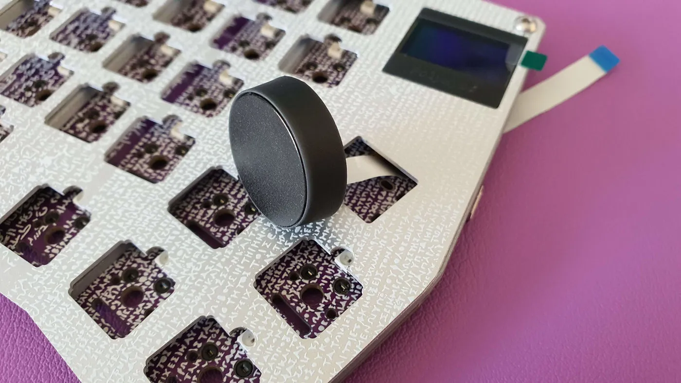
Prepare optional rotary encoder (if using)
If you are using an Alps EC11 encoder, place it on the PCB and temporarily fit the plate on top to verify it clears. Add a strip of Kapton tape over the legs if they come close to the aluminum plate.
If you are using an EVQWGD001 encoder, clip away the last pin before fitting it. Do not solder it yet — fit the plate first to check alignment.
-
Prepare optional Pimoroni trackball (if using)
Solder the header pins without the plastic distance spacer (push the spacer off with pliers after soldering, or insert pins from the front and clip the plastic from the back). Apply Kapton tape to the back of the trackball board, then solder it to the PCB flush to the front surface (expect 1–2mm gap). Cover the front of the trackball with Kapton tape or other insulating material to prevent shorts against the aluminum plate.
-
Prepare optional Cirque trackpad (if using)
Remove R1 from the back of the trackpad PCB to switch it from SPI to I2C. Connect the 12-pin FPC cable to the trackpad (note the pin 1 marker). Place the trackpad in its 3D-printed holder and secure with a small amount of adhesive. Do not connect to the PCB yet — that comes in step 6.
-
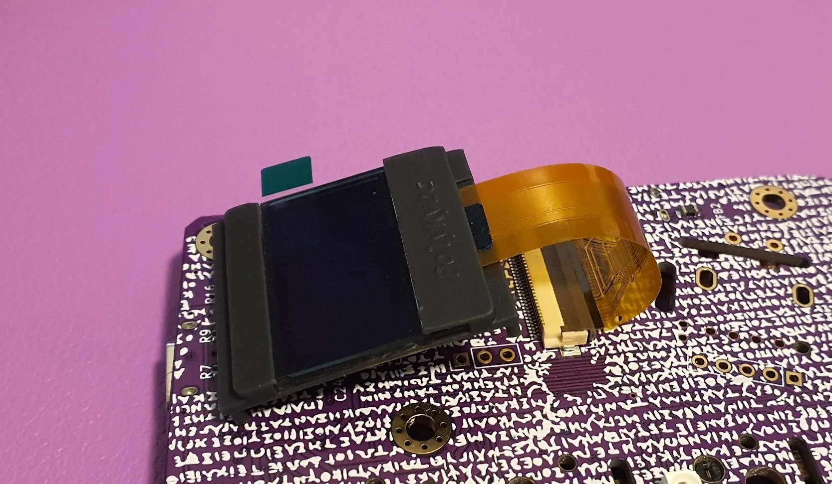
Install the status display
Insert the 0.96” status display into its holder (bend the holder back and let it snap around the display). Connect the FPC cable to the socket on the PCB and lock it by lowering the brown flap on the FPC socket.
If you are not installing a status display, fit the dummy cover in its place.
-
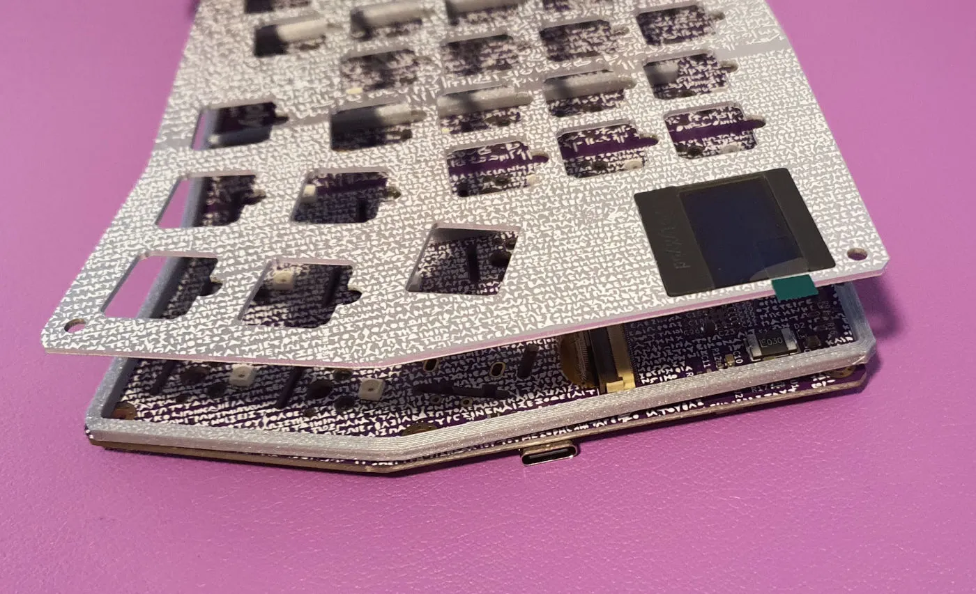
Place the spacer and fit the plate
Put the spacer on top of the PCB. Slide the plate down over the assembly, guiding the status display holder (or dummy) through the plate cutout from the back side. The plate rests on the spacer. Temporarily insert two screws at diagonal corners to align the plate and PCB.
-
Install the Cirque trackpad (if using)
Feed the FPC cable through the slot in the plate, push the trackpad holder into place (press-fit, no glue needed), then insert the FPC into the trackpad socket on the PCB and lock it by lowering the flap. Verify pin 1 alignment.
-
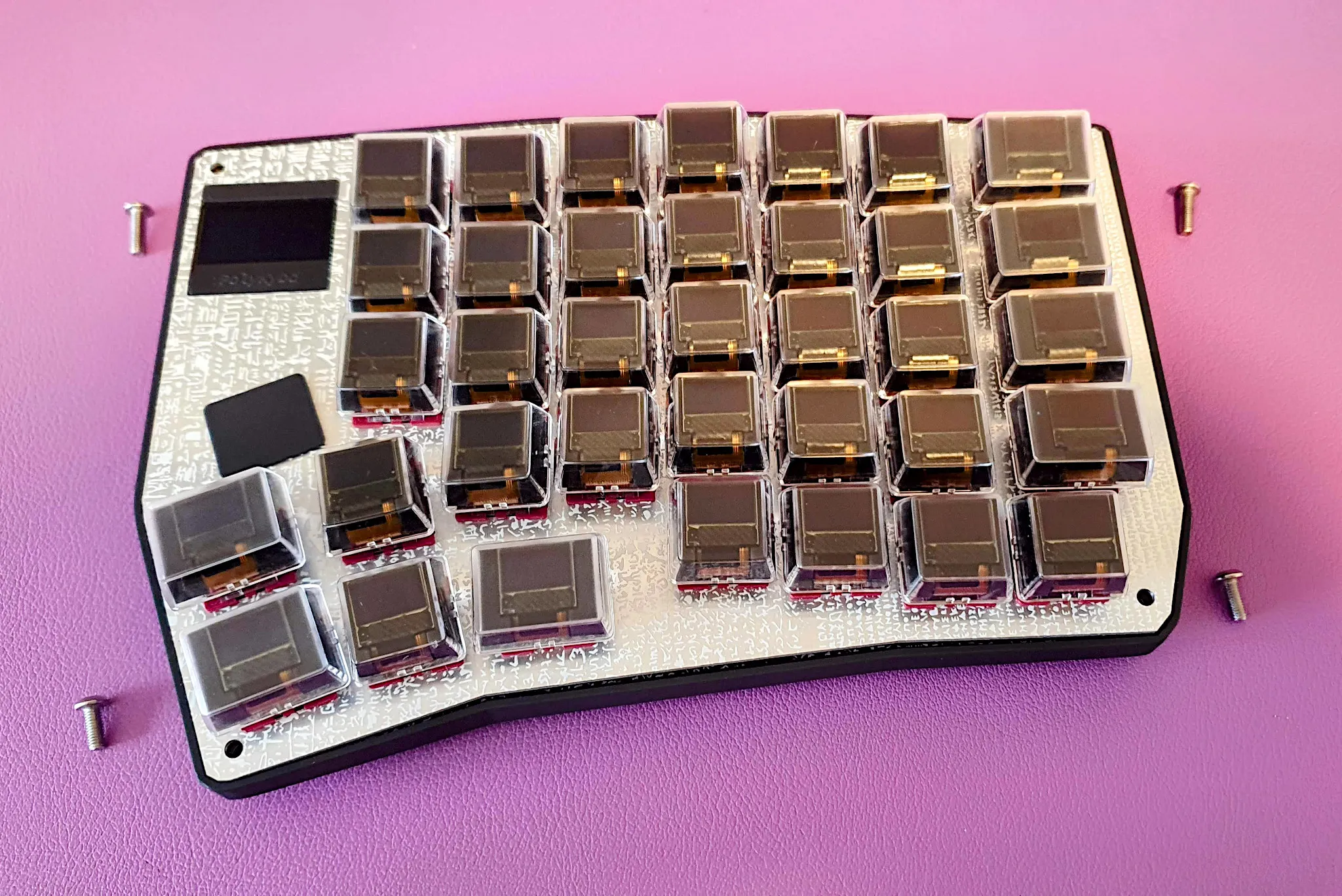
Assemble all 72 keys
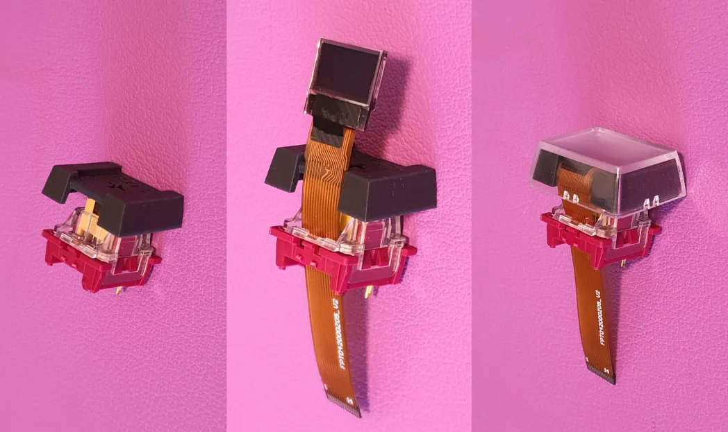
For each key:
- Place the 3D-printed stem onto the key switch
- Thread the display FPC cable through the LED slit of the switch
- Align the display against the stem
- Press the clear keycap cover over the stem — the display will slide into the stem pocket as you press it down
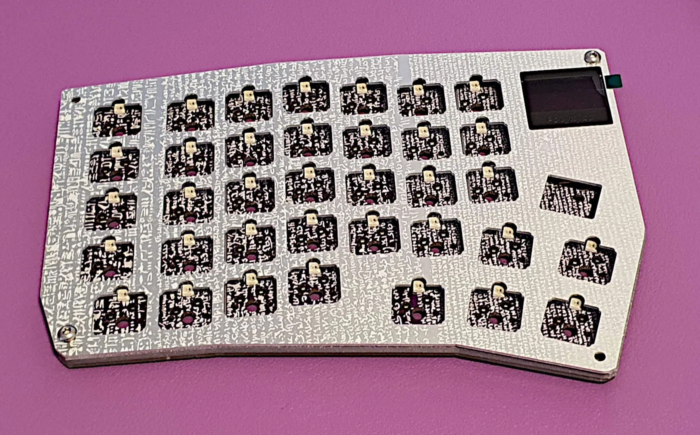
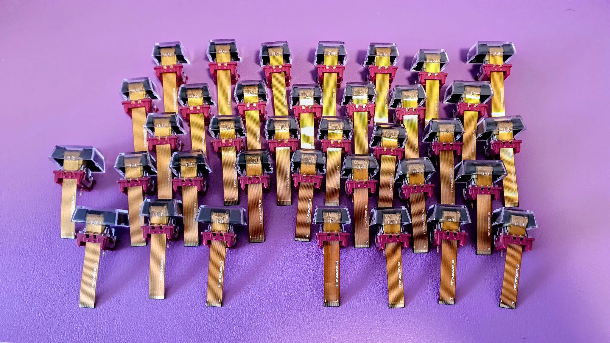
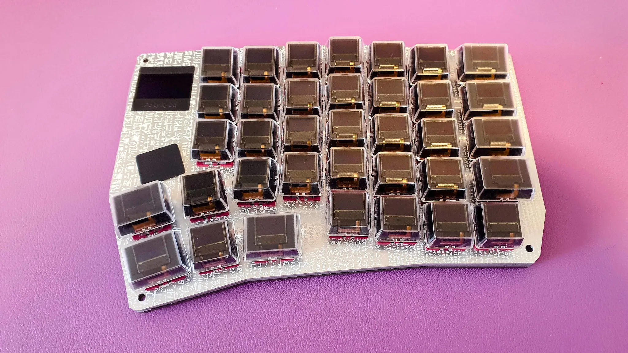
Repeat for all 72 keys. A fully prepared keyboard side of switches looks like this:
-
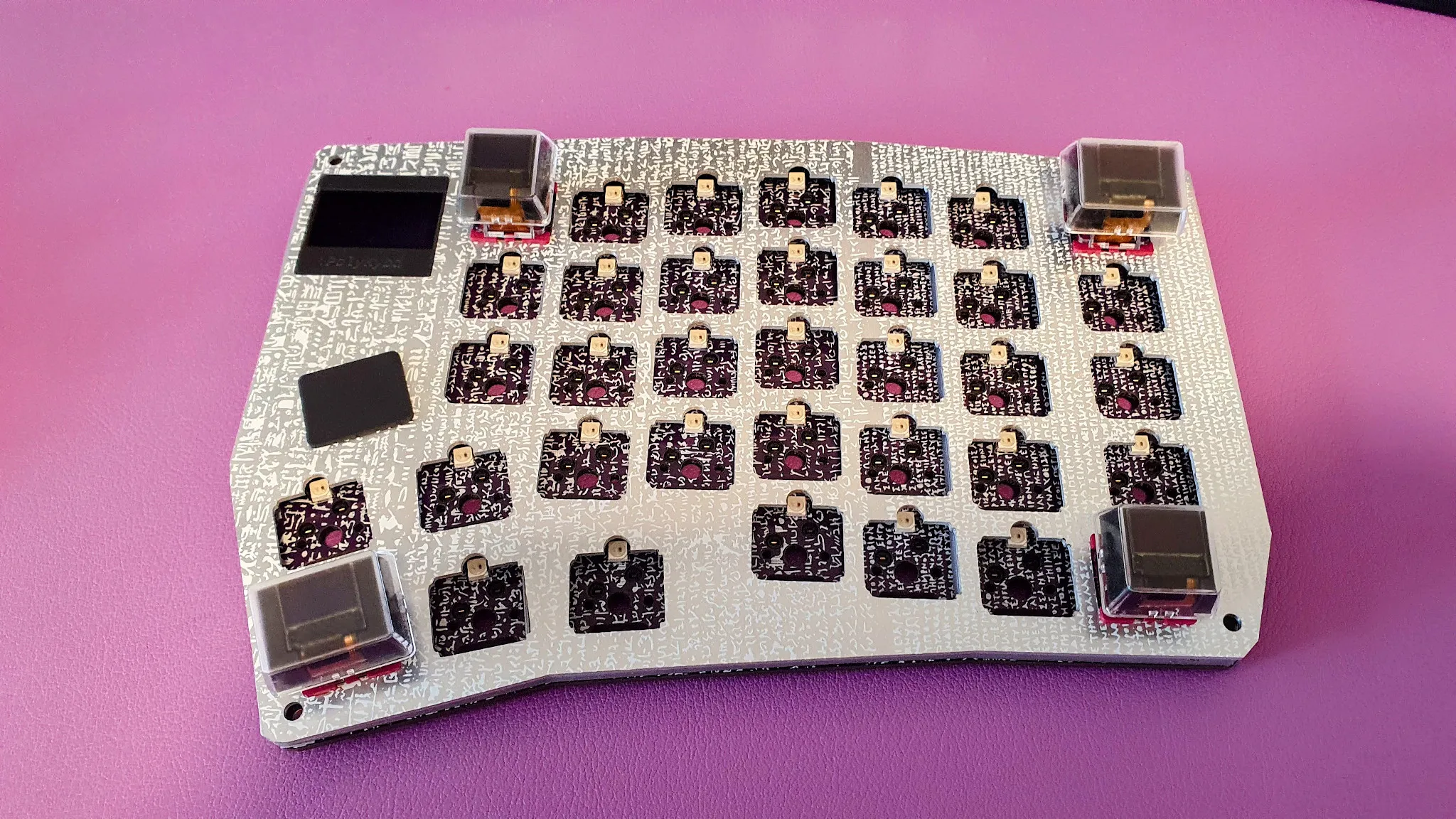
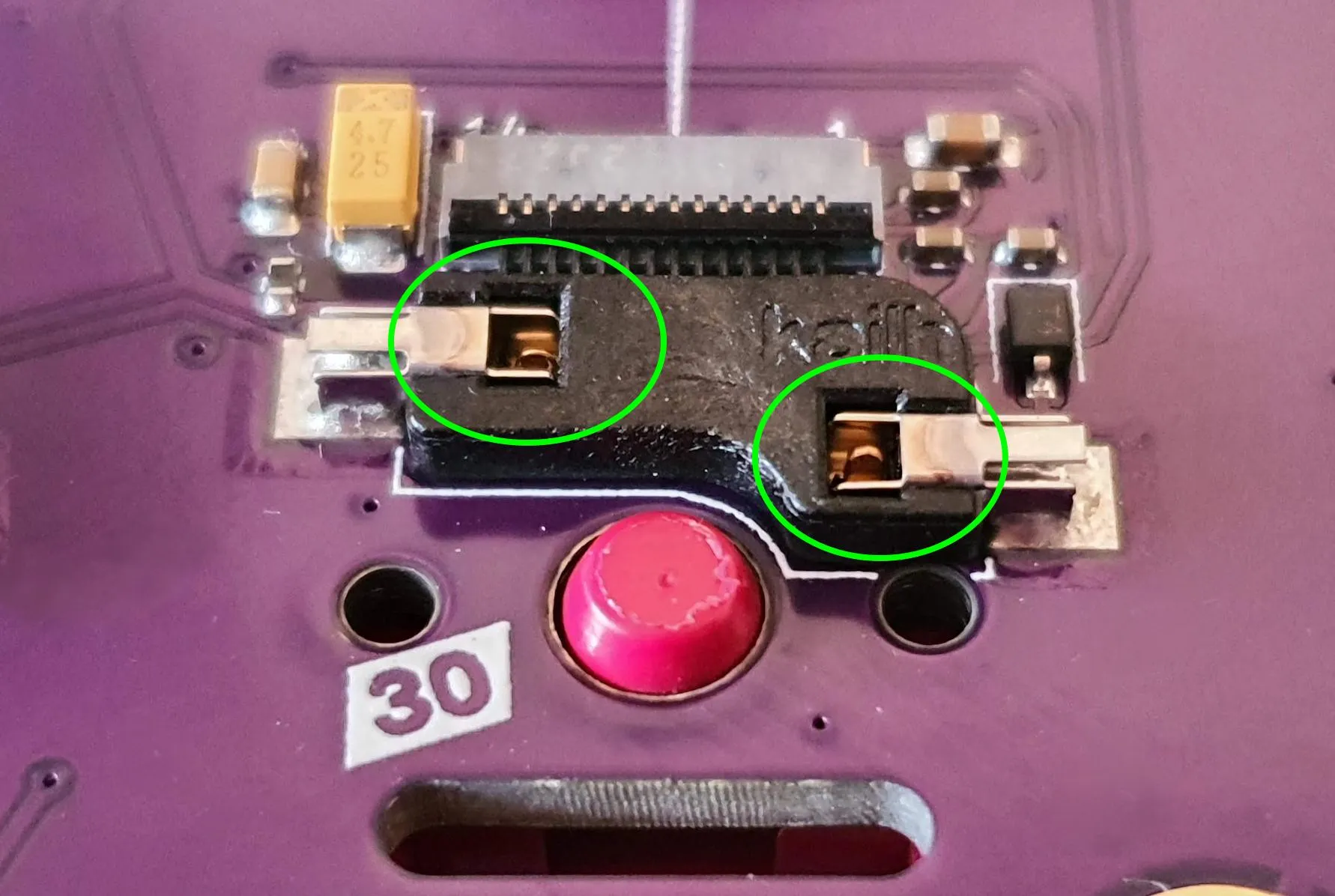
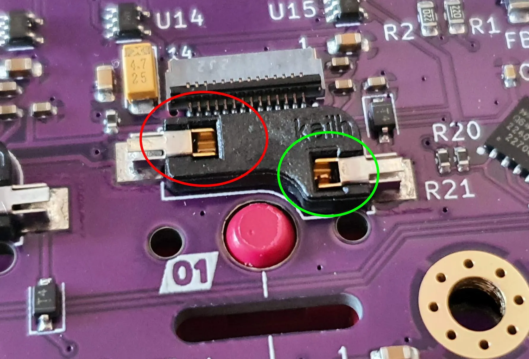
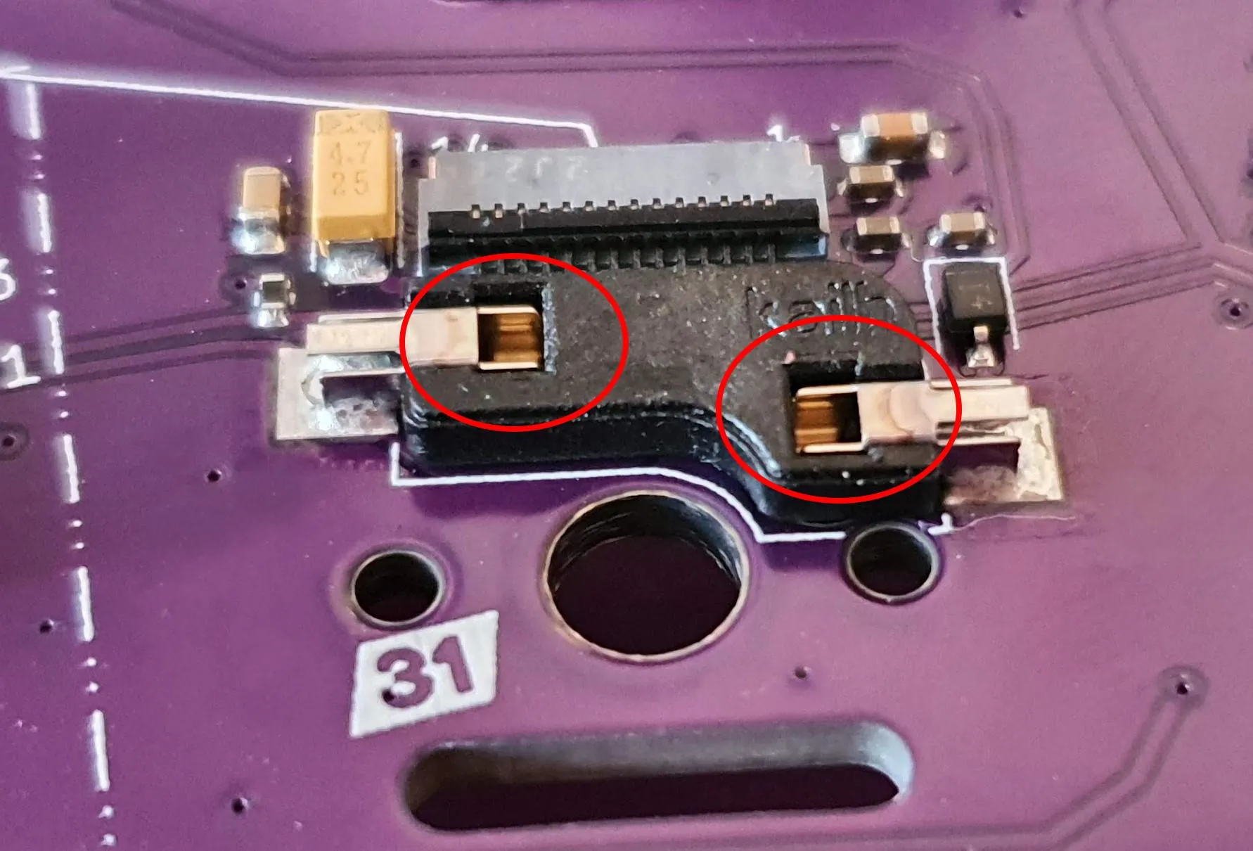
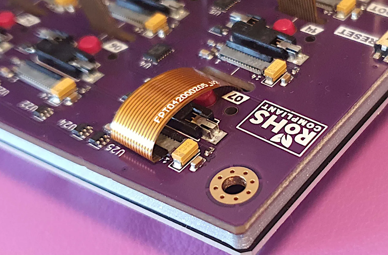
Insert corner key switches
Insert one assembled switch at each corner first to lock the alignment of plate and PCB:
- Feed the FPC into the PCB slot
- Push the switch straight down into the hot-swap socket
Check from the back that both pins are visible — they confirm the switch is fully seated:
-
Insert remaining switches
Working from the corners inward, insert all remaining assembled switches. Feed each FPC cable through its PCB slot before seating the switch body.
-
Solder the rotary encoder (if using)
With all switches seated and the plate locked in position, solder the encoder pins and trim any excess lead length on the back.
-
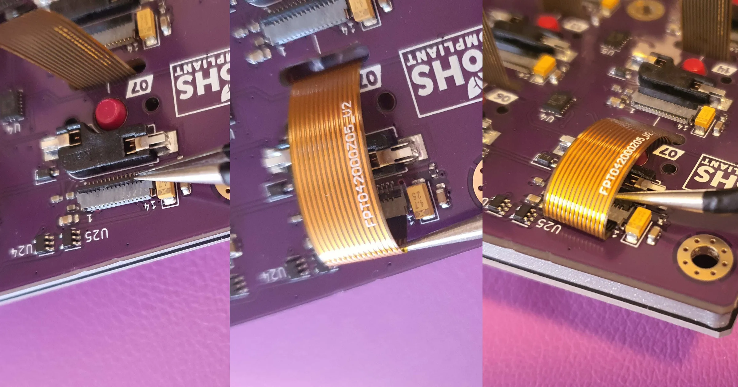
Connect FPC cables to the PCB
For each switch, open the FPC socket flap (brown lever), insert the FPC cable with the contacts facing down, and close the flap to lock it. The display should light up when powered.
-
Install M3 nuts into case corners
Press the M3 hex nuts into the corner pockets in the 3D-printed case. They should be a firm press fit. If they are loose, a small drop of CA glue will secure them.
-
Lower the PCB assembly into the case
Set the PCB+plate assembly into the case. The PCB should sit flush with the case interior walls. If it does not fit, check that all switch FPC cables are routed inside the case and not caught on the walls.
-
Screw the case together
Insert one M3×10 screw at each corner and tighten until snug. Do not overtighten — resin can crack.
-
Flash the firmware
See Flashing the Firmware for the full procedure.
-
Connect both halves
Connect the short USB-C cable between the two halves. Connect the long USB-C cable from the left half to your computer.
-
Test all keys
Open a text editor and verify that every key registers. Use the QMK key tester (via PolyKybdHost or the QMK website) to check every key systematically.
-
Install PolyKybdHost
See Installation to install the host software and bring the per-key displays to life.